What is the relationship between air receiver pressure and air storage capacity? Pressure determines how much compressed air can be stored and delivered within a usable pressure range, while receiver volume determines how much air can be stored at a given pressure. These two parameters work together, but they are not interchangeable: increasing pressure does not automatically provide the same operational benefits as increasing tank volume, and selecting a larger tank does not compensate for an inadequate compressor or an incorrectly designed system.
To select an appropriate air receiver, engineers must consider compressor output, peak air consumption, acceptable pressure drop, required backup duration, operating pressure, and applicable pressure-vessel safety requirements. A properly sized receiver stabilizes system pressure, supports intermittent demand, reduces unnecessary compressor cycling, and provides a buffer during temporary supply shortages. However, the final design should be based on engineering calculations and actual operating conditions rather than a single rule of thumb.
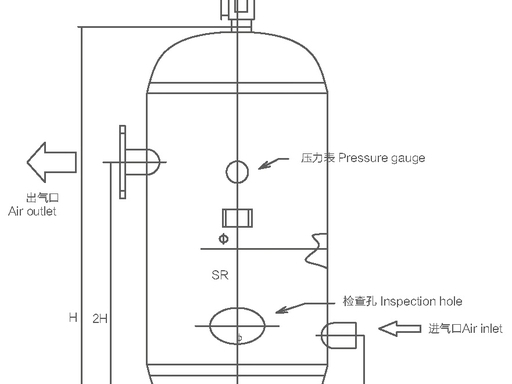
An air receiver is a pressure vessel designed to store compressed air for use in pneumatic equipment, industrial machinery, and compressed-air distribution systems. It is commonly installed downstream of an air compressor, although additional receivers may be positioned near specific applications to accommodate localized demand.
An air receiver performs several important functions. It stores compressed air, reduces rapid pressure fluctuations, helps accommodate short periods of high air consumption, and provides additional time for compressors and control systems to respond to changing demand. Depending on its position and the overall system design, it can also help separate moisture from compressed air before the air reaches downstream treatment equipment.
Air receivers are widely used in manufacturing plants, automotive workshops, food-processing facilities, pharmaceutical production, construction equipment, packaging lines, and other applications that depend on reliable pneumatic power.
Although receivers may look like simple steel tanks, their design involves pressure-vessel engineering, material selection, welding quality, corrosion protection, drainage arrangements, and pressure-relief safeguards. Their rated capacity and allowable working pressure must therefore be evaluated separately.
Air receiver pressure describes the pressure of the compressed air contained inside the vessel. It is normally expressed in bar, kilopascals (kPa), megapascals (MPa), or pounds per square inch (psi).
Industrial users commonly refer to a compressor operating at 8 bar or approximately 116 psi. However, it is important to distinguish between the pressure produced by the compressor, the pressure inside the receiver, and the pressure actually available at the point of use.
These pressures may differ because of compressor control settings, pipe friction, filters, dryers, regulators, and sudden changes in demand. For example, a receiver may contain air at 8 bar while a pneumatic tool receives only 6.5 bar after losses through the distribution network and local pressure regulation.
Engineers should also distinguish between gauge pressure and absolute pressure. Gauge pressure is measured relative to atmospheric pressure, whereas absolute pressure includes atmospheric pressure.
The distinction matters when calculating how much air a receiver can deliver. Gas-law calculations use absolute pressure, even when industrial pressure gauges display gauge pressure.
Air receiver capacity generally refers to the internal geometric volume of the vessel, usually expressed in liters or cubic meters. Common industrial sizes include 100 L, 300 L, 500 L, 1,000 L, and larger custom-designed vessels, depending on the application.
However, the volume of the tank is not the same as the amount of usable compressed air it contains.
A 500 L receiver operating at 8 bar gauge does not simply contain 500 L of air at atmospheric pressure. Under an idealized calculation at the same temperature, its stored gas inventory corresponds to approximately nine times the amount of air that would occupy the same volume at atmospheric pressure, because 8 bar gauge is approximately 9 bar absolute.
Even this figure does not represent the entire usable air supply. The receiver cannot necessarily be discharged to atmospheric pressure while continuing to meet the operating requirements of connected equipment. The usable quantity depends on the pressure at which air storage begins and the minimum pressure at which the application can still operate correctly.
Consequently, engineers should evaluate receiver capacity in relation to the usable pressure range and actual air demand, rather than relying on tank volume alone.
For a fixed volume of gas at approximately constant temperature, the ideal gas law indicates that the amount of gas is proportional to its absolute pressure.
This relationship can be expressed as:
[ P_{\mathrm{abs}}V=nRT ]
Where:
- (P_{\mathrm{abs}}) is absolute pressure.
- (V) is the internal volume of the receiver.
- (n) is the amount of gas in moles.
- (R) is the universal gas constant.
- (T) is the absolute temperature.
For an air receiver with a fixed volume and relatively stable temperature, increasing absolute pressure increases the quantity of air stored in the vessel.
Nevertheless, the relationship is not a direct one between gauge pressure and usable air capacity. Absolute pressure must be used in the gas equation, and the amount of air available to equipment depends on the permitted pressure drop.
For example, a receiver operating between 9 bar absolute and 7 bar absolute has a smaller usable pressure range than a receiver operating between 9 bar absolute and 3 bar absolute. The latter can theoretically release more air before reaching its lower pressure limit, although the connected equipment may not be capable of operating at such a low pressure.
Receiver volume and operating pressure are separate design parameters. A larger receiver provides more storage space, but it does not automatically increase the pressure generated by the compressor.
If a compressor delivers air at a maximum operating pressure of 8 bar gauge, installing a larger receiver does not transform the compressor into a 10 bar unit. The compressor, pressure controls, vessel rating, and system configuration determine the achievable operating conditions.
Similarly, a smaller receiver may reach the compressor's pressure setpoint quickly, but it may also experience rapid pressure fluctuations when several pneumatic devices operate simultaneously.
The appropriate solution depends on the actual problem. If the compressor has sufficient output but the system experiences brief demand peaks, additional storage may help. If average air consumption consistently exceeds compressor output, a larger receiver will only delay the pressure decline.
Increasing system pressure may increase the amount of air stored in a receiver of a given size, but it can also increase energy consumption, leakage losses, and mechanical stress on equipment.
Compressed-air systems should operate at the lowest pressure that reliably satisfies the requirements of their most demanding legitimate application. The Compressed Air and Gas Institute (CAGI) identifies demand, pressure, and air quality as key parameters in compressed-air equipment selection. It also emphasizes that unnecessarily high pressure can undermine energy efficiency.
Higher pressure is therefore not a substitute for correct receiver sizing, sufficient compressor capacity, or appropriate distribution-system design.
A preliminary selection method is to relate receiver volume to compressor delivery. Some practical guidelines suggest choosing a receiver with a volume equal to approximately one-third to one-fifth of the compressor's rated air delivery per minute, with the appropriate unit conversion understood.
For example, if a compressor delivers 1,500 L/min of free air, this rule of thumb would suggest a receiver in the approximate range of 300–500 L.
However, this simplified approach is not a universal engineering standard. It does not directly account for the pressure range, peak demand, compressor control strategy, acceptable pressure drop, or the duration for which stored air must support production.
It is most useful as an initial estimate for relatively straightforward installations. A detailed design should use the actual system requirements and a receiver-sizing calculation.
A more technically useful method calculates the receiver volume needed to supply a specified air demand for a defined period while pressure falls from an initial value to a permitted minimum.
For an approximate isothermal calculation with no compressor contribution during the discharge period:
[ V=\frac{T \times C \times P_{\mathrm{atm}}}{P_1-P_2} ]
Where:
- (V) = required receiver volume in the selected volume unit.
- (T) = required supply duration in minutes.
- (C) = air demand expressed as free-air flow per minute.
- (P_{\mathrm{atm}}) = atmospheric pressure in the same pressure units.
- (P_1) = initial receiver gauge pressure.
- (P_2) = minimum permitted receiver gauge pressure.
This form of the equation is commonly used in compressed-air system design guidance, including the U.S. Department of Energy's Improving Compressed Air System Performance: A Sourcebook for Industry. The equation assumes that temperature effects can be approximated as constant and that the compressor contributes no air during the discharge interval.
If the compressor continues running, the calculation must account for the difference between demand and compressor supply. The usable supply rate is then approximately the net air deficit, rather than total demand.
Suppose a manufacturing process requires 1,000 L/min of free air for 30 seconds beyond the available compressor supply. The receiver starts at 8 bar gauge, and the system must remain above 6 bar gauge.
Assume atmospheric pressure is approximately 1 bar and use the idealized constant-temperature equation.
First, convert the duration into minutes:
[ T=\frac{30}{60}=0.5\text{ min} ]
Next, calculate the required volume:
[ V=\frac{0.5\times1000\times1}{8-6} ]
[ V=250\text{ L} ]
The theoretical minimum receiver volume is approximately 250 L under these assumptions.
In practice, an engineer would also evaluate the actual compressor contribution, the receiver's initial pressure, local pressure losses, temperature changes, piping volume, valve restrictions, demand variability, and the safety margin required by the application. A nominal 250 L tank may therefore be insufficient if the stated pressure range is measured at the receiver but the equipment requires 6 bar at a distant point of use.
This example illustrates why a calculated result should be treated as a design starting point, not an automatic purchasing specification.
Some factories need stored air to support critical equipment when a compressor fails, undergoes maintenance, or takes time to restart.
In this case, receiver sizing should be based on the essential air demand that must continue during the interruption and the minimum required operating pressure.
A simplified calculation is:
[ V=\frac{T \times C \times P_{\mathrm{atm}}}{P_1-P_2} ]
Suppose essential equipment consumes 300 L/min of free air and must continue operating for five minutes. If the usable pressure range is from 8 bar gauge down to 6 bar gauge, the approximate receiver volume is:
[ V=\frac{5\times300\times1}{8-6} =750\text{ L} ]
The result suggests a theoretical receiver volume of 750 L, before engineering allowances and system-specific adjustments.
This approach is especially relevant to automated production lines, instrument-air applications, emergency control functions, and processes in which an abrupt loss of pneumatic supply could damage products or create operational hazards.
However, stored compressed air should not be assumed to provide an indefinite emergency supply. If continued operation is safety-critical, engineers should evaluate compressor redundancy, backup power, independent air supplies, and fail-safe equipment behavior.
Different methods suit different operating conditions. The following table summarizes their intended uses and limitations.
| Sizing approach | Main input | Best application | Main limitation |
|---|---|---|---|
| Compressor-output rule of thumb | Compressor delivery rate | Preliminary equipment selection | Does not fully account for demand peaks or pressure range |
| Demand-and-pressure-drop calculation | Air demand, duration, initial and minimum pressure | Temporary demand peaks | Requires accurate demand and pressure data |
| Shutdown-duration calculation | Essential demand and required backup time | Short interruptions and maintenance planning | Cannot replace a reliable backup-air strategy |
| Compressor-cycle analysis | Control settings and compressor delivery | Reducing excessive start-stop cycling | Requires knowledge of compressor controls |
| System measurement and simulation | Actual demand profile, pressure trends, operating schedule | Complex industrial installations | Requires instrumentation and engineering analysis |
A competent system designer should select the method that corresponds to the actual operational objective. In a variable-demand factory, several approaches may need to be combined.
The receiver's maximum allowable working pressure must be suitable for the maximum pressure it can experience under the installed system configuration.
For example, a compressor nominally operating at 8 bar gauge may be configured with a pressure cut-out above its normal operating setpoint. If the receiver is connected directly to that compressor, the vessel and protective devices must be suitable for the actual maximum pressure and foreseeable operating conditions.
The receiver should not be selected solely because its nominal pressure matches the compressor's normal discharge pressure. Engineers must review the compressor's maximum pressure, control settings, relief-device configuration, and applicable vessel design requirements.
If a system needs a pressure-reducing valve to supply lower-pressure equipment, the receiver's pressure rating must still be based on the pressure that can reach the vessel, not merely the reduced pressure delivered downstream.
An air receiver rated for 8 bar gauge may be suitable for a compressor system whose maximum permissible operating pressure does not exceed the receiver's rating, provided the entire system has been properly designed and protected.
However, an 8-bar receiver is not automatically appropriate for every compressor marketed as an 8-bar unit. The meaning of the compressor rating, its control settings, transient conditions, and the vessel's marked allowable working pressure must all be verified.
The reverse is also important: a receiver rated for 10 bar gauge may be used in a system normally operating at 8 bar gauge if the vessel is compatible with the installation and all applicable requirements are satisfied. Its higher pressure rating does not mean that the compressor should operate at 10 bar.
A higher-rated receiver may be reasonable where it offers design flexibility or meets a documented engineering requirement. It should not be purchased merely on the assumption that a higher pressure rating automatically improves system performance.
Operating a compressed-air system at a higher pressure than necessary can increase compressor energy consumption and leakage rates. It may also increase the load on downstream equipment, regulators, seals, hoses, and fittings.
For this reason, engineers should distinguish between the pressure rating of the vessel and the pressure at which the system actually operates. A vessel can have a suitable safety rating without requiring the compressor to run continuously at that rating.
The correct pressure target should be determined by the minimum pressure needed by the application, the pressure losses throughout the distribution network, and the compressor's control strategy. Improving piping design, filter maintenance, and local storage can sometimes solve low-pressure problems without raising the entire system's operating pressure.
Industrial air demand is rarely constant. Pneumatic cylinders, impact tools, blow-off nozzles, packaging machinery, and automated valves can create short periods of high consumption.
When demand rises faster than the compressor can respond, system pressure may fall. A properly sized receiver releases stored air during these periods, helping to reduce pressure fluctuations.
The receiver therefore acts as a buffer between air production and consumption. It does not create additional compressed air, but it allows the system to manage differences in timing between supply and demand.
Receivers can also influence compressor cycling and control stability. A small receiver may experience rapid pressure changes, causing a load/unload compressor to switch operating states frequently or a fixed-speed compressor to start and stop more often than intended.
Excessive cycling can increase wear on motors, contactors, valves, and other components. A larger receiver may provide more time between switching events, depending on compressor type and control logic.
Nevertheless, there is no single receiver-volume ratio that guarantees acceptable cycling for every installation. Compressor manufacturers' requirements, control settings, operating demand, and the number of compressors must be considered together.
CAGI's compressed-air system guidance emphasizes evaluating the actual demand profile and selecting equipment around measured or calculated system needs rather than relying solely on simple rules of thumb.
Some applications consume a large quantity of air for a few seconds but operate intermittently. Examples include pneumatic presses, shot-blasting equipment, certain packaging systems, and industrial cleaning processes.
Installing a dedicated receiver close to the high-demand equipment can reduce the impact of these events on the rest of the plant. The dedicated receiver is charged gradually and then releases air during the short demand peak.
This arrangement may reduce the need to raise the pressure of the entire compressed-air network. It can also help protect other equipment from temporary pressure drops.
The receiver must be sized to cover the relevant demand event, and the connecting pipework, check valves, and flow restrictions must be designed to support the intended charging and discharge rates.
Compressed air leaving a compressor often contains water vapor and, depending on the compressor and treatment arrangement, liquid moisture or oil contamination. As the air cools, some water vapor may condense.
An air receiver can provide a location where part of this liquid separates from the airflow and collects at the bottom of the vessel. Effective moisture removal depends on temperature, pressure, airflow patterns, and the wider air-treatment system.
Receivers should therefore be installed with appropriate drainage arrangements. Manual drains require regular attention, while automatic drains can reduce the risk of accumulated condensate when properly selected and maintained.
OSHA's air-receiver requirements include a drain at the lowest point of the vessel or suitable automatic drainage arrangements, with drainage frequent enough to prevent excessive liquid accumulation. The applicable legal and technical requirements depend on the installation's jurisdiction and use.
A receiver is commonly installed near the compressor, but the best arrangement depends on the system's operating characteristics.
A primary receiver near the compressor can help stabilize compressor operation and provide general storage. A secondary receiver near a high-demand application can help manage localized pressure fluctuations.
The installation should also consider access for inspection, drainage, maintenance, and safe isolation. Receivers should not be placed where corrosion, accidental impact, extreme temperatures, or inaccessible connections create unnecessary risks.
For systems requiring dry compressed air, the positions of the receiver and air dryer should be selected according to the dryer type, required dew point, and manufacturer's recommendations. There is no universal layout that suits every compressed-air installation.
Carbon steel is commonly used for industrial air receivers because it offers a practical balance of strength, manufacturability, and cost. Stainless steel may be appropriate where corrosion resistance, hygiene, or the process environment justifies its additional cost.
Material selection should consider the working environment, external corrosion exposure, condensate characteristics, internal coatings, maintenance practices, and the applicable pressure-vessel design code.
The receiver's material grade alone does not establish whether the vessel is safe. Wall thickness, forming processes, welding quality, heat treatment where required, inspection, and pressure-vessel calculations are also important.
Welded pressure vessels must be manufactured under controlled procedures suitable for the design and material. Depending on the applicable code and design category, inspection may include visual examination, dimensional checks, nondestructive examination, and pressure testing.
Purchasers should review the vessel's design documentation, nameplate, manufacturing records, applicable certification, and inspection requirements. They should also confirm that the rated pressure, temperature limits, capacity, and connections match the intended installation.
A low purchase price should not override evidence of inadequate construction quality or missing safety documentation. Since an air receiver stores energy under pressure, defects or corrosion can have serious consequences.
An air receiver should be equipped with appropriate pressure indication and overpressure protection. The pressure gauge allows operators to monitor operating conditions, while a correctly selected safety valve provides protection against pressure exceeding the permitted limit.
Under OSHA's general-industry air-receiver rule, 29 CFR 1910.169, receivers must have a readily visible pressure gauge and one or more spring-loaded safety valves. The total relieving capacity must prevent pressure from exceeding the maximum allowable working pressure by more than 10 percent under the rule's specified conditions. The standard also prohibits placing a valve between the receiver and its safety valve. These requirements are jurisdiction-specific and should not be treated as a substitute for reviewing the full applicable code.
Safety valves must be selected, installed, and maintained according to the vessel design and governing requirements. They should not be isolated, obstructed, or adjusted by unauthorized personnel.
Over time, internal corrosion can reduce vessel wall thickness, particularly where condensate remains in contact with unprotected steel. External corrosion can also develop when paint or protective coatings deteriorate.
Inspection programs should address the vessel's age, operating environment, history of repairs, drainage performance, and the examination requirements established by applicable regulations or codes.
In the United Kingdom, the Health and Safety Executive explains that qualifying pressure systems may require a written scheme of examination under the Pressure Systems Safety Regulations 2000. The scheme should identify the equipment and examination activities required, and the examinations must be carried out in accordance with that scheme by a competent person.
Operators should never attempt to repair, weld, drill, or modify a pressurized receiver without an approved engineering process and appropriate isolation. Before inspection or maintenance, the vessel must be safely isolated, depressurized, and prepared according to the relevant procedure.
A practical maintenance program should include:
- Checking the pressure gauge for clear indication and plausible readings.
- Inspecting the vessel exterior for corrosion, damage, leakage, or deteriorating coatings.
- Confirming that condensate drains function correctly.
- Checking safety-valve maintenance and examination records.
- Reviewing unusual pressure fluctuations and compressor cycling.
- Verifying that connected pipework and fittings are appropriate for the operating pressure.
- Keeping inspection, repair, and maintenance documentation up to date.
The inspection frequency should follow the manufacturer's instructions, the applicable code, and any required examination scheme. A generic calendar interval should not replace a competent assessment of the actual equipment.
A receiver selected only by applying a fixed fraction of compressor output may be too small for a plant with high intermittent demand or too large for a simple installation with stable demand.
Compressor output is an important starting point, but receiver sizing must also account for demand variation, pressure drop, control strategy, and the desired duration of support.
A larger receiver can supply air temporarily when demand exceeds compressor output. Once the stored air is depleted, however, system pressure will continue to fall if average demand remains greater than available supply.
Persistent pressure shortages require a broader assessment of compressor capacity, leaks, pipework restrictions, treatment equipment, and demand management.
A receiver with a higher rated pressure may be suitable for an installation, but the rating alone does not improve air delivery or efficiency.
Engineers should verify the maximum pressure the receiver may experience, the compressor's operating controls, the protective devices, and the applicable design requirements before specifying a vessel.
A receiver gauge may indicate sufficient pressure while a machine farther downstream experiences low pressure. Filters, dryers, regulators, long pipe runs, undersized connections, and peak demand can all contribute to pressure loss.
Pressure should therefore be measured at relevant points in the system during representative operating conditions. If the problem occurs only at a particular machine, dedicated storage or improved local distribution may be more effective than increasing pressure throughout the plant.
Before purchasing an air receiver, confirm the following information.
| Parameter | Questions to answer |
|---|---|
| Compressor output | What is the actual free-air delivery at the intended operating pressure? |
| Average demand | How much air does the plant consume during normal operation? |
| Peak demand | What is the maximum short-duration consumption, and how long does it last? |
| Initial pressure | What pressure is available in the receiver before the demand event? |
| Minimum pressure | What is the lowest pressure the connected equipment can tolerate? |
| Backup duration | Must the receiver support production during compressor shutdown or maintenance? |
| Vessel rating | Does the maximum allowable working pressure suit the installed system? |
| Air quality | Are moisture separation, filtration, and oil-control requirements addressed? |
| Drainage | Is condensate removal suitable for the operating environment? |
| Compliance | Which pressure-vessel code, inspection rules, and documentation apply? |
| Future expansion | Is the plant likely to add equipment or increase air demand? |
A qualified supplier should be able to provide the vessel's rated capacity, maximum allowable working pressure, design temperature range, connection details, material specifications, applicable certifications, and maintenance documentation. Buyers should also confirm whether additional equipment, such as a pressure gauge, safety valve, drain assembly, or mounting accessories, is included.
Air receiver pressure and capacity are closely related, but they serve different purposes. Pressure describes the operating condition of the stored air, while receiver volume determines how much gas can be stored and how much air can be delivered across a defined pressure range.
A suitable receiver must therefore be selected by considering compressor output, actual air consumption, allowable pressure drop, required support duration, pressure-vessel rating, and system safety. Simple capacity ratios can support preliminary estimates, but engineering calculations and operating data provide a more reliable basis for final selection.
For industrial users, the goal is not to purchase the largest receiver or the highest-pressure vessel available. It is to establish a safe, stable, energy-efficient compressed-air system in which the compressor, receiver, air-treatment equipment, pipework, and end-use machinery work together.
By combining appropriate sizing calculations with sound pressure-vessel design, effective condensate management, regular inspection, and correctly maintained safety devices, manufacturers and plant operators can improve reliability while controlling equipment and operating costs.
Previous: How to Improve Air Receiver Tank Quality
