Air receiver tanks are essential components of compressed air systems used in manufacturing plants, automotive workshops, construction sites, food processing facilities, pharmaceutical production, and many other industrial environments. By storing compressed air, they help stabilize system pressure, accommodate short-term fluctuations in air demand, reduce unnecessary compressor cycling, and support the reliable operation of downstream equipment. Because these tanks operate under pressure, their quality directly affects equipment safety, system efficiency, and the continuity of industrial production.
As industrial users demand higher levels of safety, reliability, and operating efficiency, air receiver tank manufacturers must continuously improve their products. Simply increasing production volume or reducing manufacturing costs is not enough. A high-quality air receiver requires appropriate material selection, sound engineering calculations, controlled fabrication processes, qualified welding, effective inspection, and comprehensive testing. Each stage contributes to the integrity of the pressure boundary and the service life of the finished vessel.
Manufacturers should therefore establish quality management systems that cover the entire product lifecycle, from supplier qualification and raw material inspection to final delivery and technical support. Investments in advanced manufacturing equipment, skilled personnel, traceable production records, and reliable testing procedures can help reduce defects and improve manufacturing consistency.
Most importantly, quality improvement must never compromise pressure vessel safety. The design pressure, allowable materials, fabrication methods, inspection scope, and acceptance criteria must comply with the applicable codes and regulations. For manufacturers, improving air receiver tank quality means creating products that consistently meet their intended service requirements while protecting operators, equipment, and the surrounding environment.
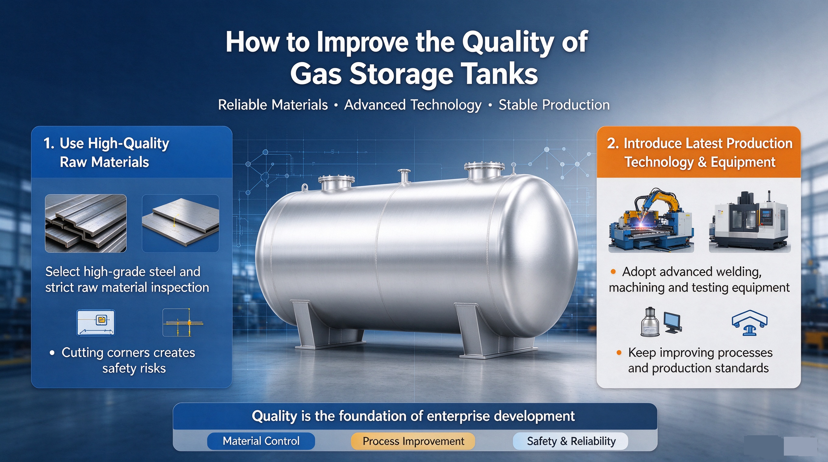
Raw material selection is one of the most important factors affecting the quality of an air receiver tank. The shell, heads, nozzles, flanges, supports, and other pressure-retaining components must withstand the specified pressure, temperature, mechanical loads, and environmental conditions throughout the vessel's intended service life. Using unsuitable materials or materials with inadequate mechanical properties can compromise the pressure boundary, even when the tank appears satisfactory during a visual inspection.
Carbon steel is widely used for conventional compressed air receivers because it offers a practical combination of strength, availability, manufacturability, and cost. Stainless steel may be appropriate for applications requiring particular corrosion resistance, cleanliness, or compatibility with the process environment. However, material selection should never be based on price or material category alone. The exact grade, thickness, toughness, weldability, and applicable design requirements must be verified against the intended operating conditions.
Manufacturers should consider the following factors when selecting materials:
- Design pressure: The material must provide the mechanical properties required by the governing pressure vessel design rules.
- Operating temperature: Allowable stresses and material behavior can vary with temperature, so the design must use appropriate material data.
- Corrosion exposure: Moisture, compressor oil, contaminants, cleaning chemicals, and outdoor environments may affect material durability.
- Weldability: The selected material must be compatible with the qualified welding procedures used during fabrication.
- Mechanical toughness: Where relevant, impact toughness and low-temperature performance should be considered.
- Availability and traceability: Materials should come from qualified suppliers and be supported by the required documentation.
Selecting suitable raw materials at the beginning of production reduces the risk of premature corrosion, fabrication defects, and nonconformities discovered during final inspection.
Purchasing steel from a reputable supplier is important, but supplier reputation alone is not sufficient to demonstrate that every delivered plate or component meets the purchase specification. Manufacturers should establish incoming material inspection procedures and verify the documentation required by the applicable code and project requirements.
Material test certificates may provide information such as the material grade, heat number, chemical composition, mechanical test results, and applicable specification. These records help demonstrate that the material meets the required characteristics. Depending on the quality plan, additional checks may include dimensional inspection, surface examination, identification marking, and positive material identification where appropriate.
Traceability should be maintained from the incoming material stage through cutting, forming, welding, inspection, and final assembly. When a steel plate is divided into several pieces, its identification should be transferred in a controlled manner so that the finished pressure vessel can be linked to the original material records.
A practical material control process includes:
- Confirming the purchase specification and approved material grade.
- Checking certificates and identification markings upon receipt.
- Inspecting plates and components for visible damage, unacceptable defects, or dimensional deviations.
- Transferring identification marks when materials are cut or processed.
- Linking material records to the vessel serial number and manufacturing documentation.
- Preventing unapproved material substitutions.
These controls reduce the likelihood of incorrect materials entering production and make subsequent quality investigations more effective.
Manufacturers frequently face pressure to offer competitive prices, especially in markets where customers compare products primarily by capacity, working pressure, dimensions, and cost. However, reducing plate thickness, using an unapproved material grade, or substituting components without engineering review can create significant safety risks.
The required wall thickness of a pressure vessel is determined by the applicable design rules and relevant factors, including design pressure, diameter, material allowable stress, weld joint efficiency where applicable, corrosion allowance, and other design conditions. It should never be reduced simply because a competitor offers a thinner tank or because the difference is difficult for a customer to observe.
Similarly, the use of a higher nominal material grade does not automatically resolve every design concern. The material must still be suitable for the temperature, fabrication process, corrosion environment, and governing code. Quality improvement should focus on achieving the required engineering performance consistently, not on making undocumented changes to the specification.
An air receiver tank is a pressure vessel, not merely a steel container designed to hold air. Its cylindrical shell, heads, nozzles, openings, supports, and other structural features must be designed to withstand the specified pressure and applicable loads. Inadequate calculations can result in excessive stress, local deformation, leakage, or catastrophic failure.
The design process should follow the pressure vessel code and regulatory framework applicable to the target market. For example, ASME Boiler and Pressure Vessel Code Section VIII provides requirements for covered pressure vessels, while other jurisdictions may require different or additional standards and approvals. Manufacturers must identify the correct code and edition rather than assuming that one certification automatically satisfies all markets.
Engineering calculations should address more than the main cylindrical shell. Depending on the design, they may need to consider:
- Shell and head thickness.
- Nozzle openings and reinforcement.
- Pressure-retaining flanges and connections.
- Weld joint requirements and efficiencies.
- Corrosion allowance.
- External loads and support reactions.
- Wind, seismic, transportation, or lifting loads where applicable.
- Temperature-related effects and material allowable stresses.
- Relevant fatigue or cyclic loading considerations.
Design calculations should be reviewed and approved by competent personnel. Changes to pressure, capacity, material, wall thickness, or nozzle configuration should be evaluated through a controlled engineering change process.
The geometry of the vessel affects pressure distribution, fabrication complexity, material consumption, and structural performance. Cylindrical shells with properly designed heads are common in air receiver manufacturing. Depending on the specification, head configurations may include ellipsoidal, torispherical, hemispherical, or other code-permitted forms.
Each configuration has different geometric characteristics and manufacturing implications. Head forming must achieve the specified shape and dimensional tolerances without unacceptable thinning, cracking, or other defects. The design must account for the actual formed geometry and the relevant thickness requirements rather than relying exclusively on the thickness of the original plate.
Nozzle placement also deserves careful consideration. Poorly located openings can complicate fabrication, inspection, drainage, or maintenance access. Manufacturers should coordinate the locations of inlet and outlet connections, pressure gauges, relief devices, drains, and access openings during the engineering stage.
A well-designed receiver should be practical to manufacture, inspect, install, operate, and maintain. Good design improves quality not only by controlling stress but also by reducing avoidable fabrication difficulties and providing sufficient access for inspection.
The quality of a receiver tank is not determined by its pressure rating alone. Its volume, connection sizes, orientation, and accessory arrangement must also suit the compressor and downstream demand. An undersized receiver may provide insufficient buffering during peak air consumption, while an incorrectly configured system may experience unnecessary pressure fluctuations or inefficient compressor operation.
Manufacturers should obtain reliable application data before recommending a model. Relevant information includes compressor capacity, operating pressure, demand variation, duty cycle, required air quality, installation space, and the arrangement of air treatment equipment. In some systems, receivers are installed before dryers to help manage wet compressed air, while additional storage downstream may support a more stable supply of treated air.
The design should also consider condensate management. Compressed air commonly contains water vapor, and cooling can cause moisture to condense inside the receiver. If the vessel lacks an effective drainage arrangement, accumulated liquid can promote internal corrosion and reduce available storage volume.
Engineering a receiver for its actual service conditions improves the practical value of the product and helps prevent problems that cannot be solved simply by using thicker steel.
Manufacturing equipment has a direct influence on dimensional accuracy, production repeatability, material utilization, and defect rates. Modern cutting systems, including appropriately configured CNC equipment, can improve the consistency of plate dimensions and opening locations. Accurate preparation reduces the need for excessive grinding or rework and helps components fit together as intended during assembly.
However, automated cutting does not eliminate the need for process control. Manufacturers must select suitable cutting parameters, maintain equipment, verify dimensional tolerances, and inspect cut edges for defects that could affect forming or welding. Edge preparation must follow the approved fabrication procedure and be compatible with the selected welding method.
Plate handling and storage are also important. Steel should be protected from unnecessary damage, contamination, and mix-ups. Components should be identified clearly, and cut pieces should be stored in a way that preserves traceability and prevents distortion.
By improving material preparation, manufacturers can reduce downstream problems such as misalignment, inconsistent weld gaps, and excessive correction during assembly. This contributes to a more stable production process and improves the consistency of finished air receiver tanks.
The cylindrical shell of an air receiver is commonly formed by rolling steel plate into the specified diameter. Accurate rolling helps control roundness and joint fit-up, while suitable head-forming equipment produces the required curvature and dimensions. Inconsistent forming can lead to excessive mismatch at joints, uneven geometry, and additional stress concentrations.
Manufacturers should establish operating parameters and inspection checkpoints for rolling and forming equipment. These controls may include verifying plate thickness, checking the formed diameter, measuring ovality where specified, and inspecting formed heads for cracks, surface damage, or unacceptable thinning.
Equipment maintenance is equally important. Worn rollers, inaccurate gauges, inconsistent hydraulic pressure, or poorly calibrated measuring devices can introduce variation into the manufacturing process. Periodic calibration and preventive maintenance help ensure that equipment continues to perform within defined tolerances.
The purpose of modernization is not simply to install more advanced machinery. It is to establish a repeatable process in which the equipment, operating parameters, trained personnel, and inspection procedures work together to produce components that conform to the approved design.
Automated or mechanized welding can improve repeatability and productivity, particularly for long longitudinal seams and circumferential joints. Depending on material thickness and production requirements, manufacturers may use processes such as submerged arc welding, gas metal arc welding, or gas tungsten arc welding. The appropriate process depends on the approved welding procedure and the actual fabrication conditions.
Automation can help maintain consistent travel speed, heat input, and weld deposition. Nevertheless, an automated process can still produce unacceptable welds if the parameters are incorrect, joint preparation is poor, consumables are unsuitable, or the equipment is not properly maintained.
Manufacturers should qualify welding procedures as required by the governing code, maintain appropriate welder or welding operator qualifications, and control welding consumables. Weld joint preparation, fit-up, preheating where required, interpass temperature, and postweld heat treatment where applicable must follow the approved procedure.
Advanced welding equipment provides the greatest benefit when it is supported by sound engineering, competent personnel, and systematic inspection. It should not be treated as a substitute for welding qualification or quality assurance.
Welding is one of the most critical manufacturing processes for a pressure vessel because the welds form part of the pressure boundary. Defects such as cracks, incomplete fusion, lack of penetration, porosity, and slag inclusions can reduce joint integrity. Under repeated pressure cycles, certain defects may grow and eventually contribute to leakage or rupture.
Manufacturers should establish and maintain welding procedure specifications and supporting qualification records where required. A welding procedure specification defines the essential parameters for a particular welding operation, including the welding process, material group, joint design, filler material, and other variables relevant to the qualification and applicable code.
Welders and welding operators must have the qualifications required for the work they perform. Qualification should match the relevant process, material, thickness, position, and other applicable requirements. Records should be controlled and made available for review when required by the quality plan.
A consistent welding system reduces variability between shifts, production batches, and individual operators. It also helps ensure that manufacturing changes are reviewed before implementation rather than being introduced informally on the shop floor.
Good welding quality begins before the welding arc is started. Incorrect alignment, excessive root gaps, contaminated surfaces, and poor edge preparation can make it difficult to achieve the required joint integrity. These problems may remain hidden beneath a weld surface and cannot always be corrected through final visual inspection alone.
Manufacturers should inspect joint preparation and fit-up before welding begins. The inspection should verify that the joint configuration matches the approved drawing and welding procedure. Relevant factors may include edge bevel, root opening, alignment, cleanliness, tack weld condition, and the positioning of adjoining components.
During welding, personnel should monitor the variables required by the approved procedure. Where specified, they should record preheat temperature, interpass temperature, consumable control, and other essential process information. Any deviation that may affect quality should be reviewed and resolved through established procedures.
Postweld inspection should identify visible imperfections, unacceptable weld profiles, undercut, surface cracking, and other discontinuities. The required inspection method and acceptance criteria must be established before production, not improvised after defects have been discovered.
Some weld defects can be repaired, but repairs must be controlled. An uncontrolled repair may introduce additional heat input, residual stress, distortion, or new discontinuities. Repeated repairs in the same area can also complicate the assessment of the finished joint.
A repair procedure should define how the defect is identified, removed, examined, rewelded, and reinspected. The repair should use an approved method compatible with the material, original welding procedure, and governing code. Additional heat treatment or inspection may be required depending on the applicable requirements.
Manufacturers should record the location, type, cause, and disposition of significant weld defects. An increasing repair rate may indicate problems with material preparation, welding parameters, operator training, or equipment condition. Root-cause analysis allows the manufacturer to correct the underlying process instead of repeatedly repairing the same type of defect.
Visual inspection is a basic but valuable part of pressure vessel quality control. It can identify surface defects, dimensional deviations, poor fit-up, visible weld imperfections, damaged coatings, incorrect component locations, and other issues that may affect manufacturing quality.
Inspection should take place at multiple stages rather than being postponed until the vessel is complete. Incoming material inspection, preweld fit-up checks, in-process examination, final visual inspection, and coating inspection each serve a different purpose. Early detection is generally less costly because defects can be corrected before additional fabrication work makes repairs more difficult.
Inspectors should use approved drawings, procedures, and acceptance criteria. Measuring instruments should be appropriate for the task and maintained in a suitable calibration system. Inspection records should identify the vessel, the relevant inspection stage, the findings, and any corrective actions.
Visual inspection cannot reveal every internal discontinuity, so it must be combined with other methods when required by the design code, contract, or risk assessment. Its greatest value comes from being integrated into the entire manufacturing process.
Non-destructive examination (NDE), also commonly called non-destructive testing (NDT), helps assess material or weld integrity without destroying the finished component. The appropriate method depends on the material, joint geometry, defect type, thickness, accessibility, governing code, and specified inspection extent.
Common methods include:
| Inspection method | Primary purpose | Typical considerations |
|---|---|---|
| Radiographic testing (RT) | Examines internal weld discontinuities using radiation-based imaging | Requires radiation controls, suitable access, and qualified interpretation |
| Ultrasonic testing (UT) | Uses sound waves to detect internal discontinuities or measure thickness | Requires suitable procedures, calibration, and qualified personnel |
| Magnetic particle testing (MT) | Detects surface and near-surface discontinuities in ferromagnetic materials | Not suitable for all material types |
| Liquid penetrant testing (PT) | Identifies surface-breaking discontinuities | Requires a clean, accessible surface and appropriate penetrant procedure |
| Visual testing (VT) | Examines visible surface condition and workmanship | Cannot independently establish the absence of internal defects |
Not every tank requires every method, and the extent of examination should not be chosen by convenience alone. The governing code, joint category, design, inspection plan, and project requirements determine what is necessary. Acceptance criteria must also be defined, and personnel should be qualified for the examinations they perform or interpret.
Manufacturers should maintain NDE reports and link them to the relevant vessel and weld locations. Where defects are repaired, the required re-examination should be completed before the vessel is accepted.
Wall thickness verification helps confirm that fabricated components meet the approved design requirements. The original plate thickness, forming process, corrosion allowance, and code-defined tolerances must all be considered when evaluating a finished vessel. A thickness measurement should not be interpreted in isolation without reference to the design documentation and applicable acceptance criteria.
Ultrasonic thickness measurement can be useful where the method is appropriate and properly calibrated. Other dimensional checks may include shell diameter, length, head geometry, nozzle position, and overall alignment. The specific inspection plan should identify which dimensions are critical and how they will be measured.
Manufacturers should also investigate repeated dimensional deviations rather than relying solely on final rework. Consistent errors may indicate problems with cutting equipment, forming tools, measurement methods, or operator training. Correcting the process can reduce production waste and improve the quality of subsequent vessels.
Pressure testing is an important stage in verifying the integrity of a completed pressure vessel. Hydrostatic testing uses a liquid, commonly water, as the test medium. The test pressure, procedure, duration, and acceptance criteria must be established according to the applicable design code, material properties, temperature conditions, and project requirements.
A universal pressure multiplier should not be assumed for every air receiver. Although certain specifications use familiar ratios between test pressure and design pressure, the correct value must be determined from the governing rules and the actual vessel design. Manufacturers should never choose a test pressure simply by copying the practice used for a different tank.
Before hydrostatic testing, the vessel should be prepared according to an approved procedure. The procedure should address test equipment, filling and venting, instrumentation, pressurization sequence, inspection access, and personnel safety. After the required pressure is reached, the vessel should be examined according to the specified method for leakage, abnormal deformation, or other unacceptable indications.
Test results must be documented and reviewed before the vessel is released. If a vessel fails, the cause must be investigated and any repair, re-examination, and retesting must be completed according to the applicable requirements.
Pneumatic testing may be considered when hydrostatic testing is impractical or unsuitable, but it requires particular caution. A compressed gas stores significantly more recoverable energy than a liquid under comparable test conditions, increasing the potential consequences if a failure occurs during the test.
Pneumatic testing should therefore be conducted only when permitted by the governing code and supported by an approved engineering procedure and risk assessment. The procedure should define the test pressure, pressurization stages, exclusion zones, barriers where required, inspection arrangements, and emergency response measures. Personnel should not approach or inspect a pressurized vessel in ways that violate the approved safety procedure.
Manufacturers should not use pneumatic testing as a shortcut to avoid the planning required for hydrostatic testing. The selected method must satisfy the applicable code and provide an acceptable level of safety for the test environment.
The quality of an air receiver extends beyond the pressure boundary. The completed assembly must include the required safety accessories and identification information for its intended service. Depending on the applicable regulations and system design, these may include a pressure-relief device, pressure gauge, drain connection, and other specified components.
The relief device must be suitable for the vessel and system, with the required set pressure and capacity established according to the applicable rules. Installation should not allow an unintended isolation arrangement to prevent the device from protecting the vessel. The discharge arrangement should also be evaluated to avoid exposing personnel to hazards.
A pressure gauge should have an appropriate range and accuracy for the application. The drain should allow accumulated condensate to be removed safely. The nameplate and required documentation should accurately identify the vessel and provide the information required by the governing framework.
Final inspection should confirm that accessories are installed correctly, identification is legible, and the supplied configuration matches the approved specification. These checks help ensure that a well-manufactured vessel is also ready for safe integration into the compressed air system.
Internal corrosion is an important concern for many compressed air receivers because moisture can condense inside the vessel. Depending on the compressor, operating conditions, and air treatment arrangement, the condensate may also contain oil and other contaminants. If liquid remains at the bottom of the tank for extended periods, corrosion can gradually reduce the pressure-retaining wall thickness.
The internal protection strategy should reflect the material, air quality requirements, condensate chemistry, and intended operating environment. Options may include a suitable internal coating, corrosion-resistant materials, or a system design that effectively manages moisture. Not every receiver requires the same coating, and any coating used must be compatible with the service conditions and application method.
Surface preparation is critical. Oil, rust, scale, dust, and other contaminants can reduce coating adhesion. Manufacturers should establish requirements for cleaning, surface preparation, application conditions, curing, and final inspection. Coating thickness and other acceptance criteria should follow the coating specification.
An internal coating should not be treated as a substitute for correct drainage or appropriate wall thickness. Corrosion protection is most effective when it forms part of an integrated design and maintenance strategy.
External coatings protect the vessel from atmospheric moisture, handling damage, and environmental exposure. The appropriate coating system depends on whether the receiver will be installed indoors, outdoors, in a humid production area, or in a more aggressive industrial environment.
Manufacturers should control surface preparation, primer selection, coating compatibility, application thickness, curing, and handling after finishing. Poor surface preparation or inadequate curing may result in blistering, peeling, or premature corrosion even when a high-quality coating material has been selected.
Coating inspection should take place before shipment, and any damage caused during lifting or transport should be repaired using an approved method. Where the project requires special corrosion protection, the manufacturer should document the system used and the relevant inspection results.
A durable finish improves product appearance, but its primary function is protection. A visually attractive tank is not necessarily a reliable pressure vessel unless the underlying material, welds, design, and testing also meet the required standards.
A quality management system provides the framework for ensuring that manufacturing activities are performed consistently and that deviations are identified and resolved. Rather than relying on the final inspector to catch every defect, manufacturers should build quality controls into each stage of production.
A typical air receiver manufacturing quality plan may include the following stages:
- Contract review: Confirm design pressure, capacity, materials, dimensions, standards, accessories, documentation, and delivery requirements.
- Design approval: Verify calculations, drawings, material specifications, and applicable regulatory requirements.
- Supplier control: Qualify raw material and component suppliers and establish incoming inspection requirements.
- Material preparation: Maintain identification, dimensional accuracy, and suitable surface condition.
- Forming and assembly: Check shell geometry, head dimensions, fit-up, and nozzle locations.
- Welding: Use qualified procedures, qualified personnel, and controlled welding parameters.
- Inspection and NDE: Complete examinations according to the approved inspection plan.
- Pressure testing: Perform the required test and document the results.
- Finishing: Inspect coatings, accessories, identification, and final configuration.
- Final release: Review all required records and confirm that nonconformities have been resolved.
This structured approach improves consistency and helps manufacturers identify defects before they become expensive or dangerous problems.
An inspection and test plan (ITP) defines the inspections and tests required at key manufacturing stages. It should identify the activity, applicable procedure, acceptance criteria, responsible party, required records, and any customer or third-party inspection points.
For example, a customer may require notification before pressure testing or welding inspection. The plan should specify these requirements in advance so that inspection activities do not disrupt production or occur after the relevant evidence has become inaccessible.
An ITP also helps distinguish mandatory code requirements from additional project-specific requirements. This distinction is important because over-inspection can create unnecessary costs, while under-inspection can leave significant risks unaddressed. The objective is to provide sufficient, documented evidence of compliance without replacing engineering judgment with indiscriminate testing.
Quality records should be reviewed before shipment. Missing certificates, unresolved inspection findings, or incomplete test reports should be treated as release issues rather than administrative details that can be corrected after delivery.
A quality system is most effective when it helps prevent repeated defects. Manufacturers should record nonconformities, identify their causes, implement corrective actions, and verify whether those actions are effective. Simply repairing a defective tank may restore the individual product, but it does not necessarily prevent the same problem from occurring in future production.
Useful quality indicators include weld repair rates, first-pass inspection acceptance, pressure test failures, coating defects, material documentation errors, customer complaints, and warranty claims. Trends can reveal recurring problems that are difficult to detect through isolated inspections.
For example, a rising weld repair rate may indicate a need to review joint preparation, welding parameters, equipment condition, or personnel training. Repeated coating failures may suggest inadequate surface preparation or unsuitable curing conditions. A structured review helps management prioritize improvement measures according to their impact on product quality and safety.
Advanced equipment and documented procedures are valuable only when employees understand how to use them correctly. Air receiver manufacturing involves several specialized activities, including material handling, forming, welding, dimensional inspection, NDE, pressure testing, coating, and documentation. Each activity requires appropriate training and a clear understanding of the quality requirements.
Manufacturers should define competence requirements for each position. Welders, welding operators, inspectors, and NDE personnel should hold the qualifications required by the applicable code or procedure. Other employees should receive training in their assigned tasks, including safe equipment operation, defect identification, traceability, and nonconformity reporting.
Training should not be limited to new employees. Changes in materials, equipment, procedures, or regulations may require refresher training or updated qualifications. Supervisors should also verify that employees follow approved procedures during actual production rather than relying solely on training records.
A technically capable workforce helps identify problems earlier, reduces avoidable rework, and supports more consistent production quality.
Quality improvement requires cooperation between engineering, purchasing, production, inspection, maintenance, and management. If employees are rewarded only for production speed, they may feel pressure to bypass inspection or accept deviations. A stronger quality culture recognizes that meeting safety and specification requirements is part of productivity, not an obstacle to it.
Employees should be encouraged to report defects, equipment problems, and unclear instructions without fear of inappropriate retaliation. Responsibilities for reviewing and approving deviations should be clearly defined. Production targets should not override mandatory safety checks or pressure vessel code requirements.
Management should also review quality performance regularly and ensure that corrective actions receive adequate resources. When employees understand how their work affects pressure boundary integrity, they are more likely to take ownership of product quality.
The quality of an air receiver depends partly on the reliability of purchased materials, valves, gauges, relief devices, flanges, and other components. A manufacturer that maintains strong internal processes can still encounter quality problems if its suppliers provide unsuitable or inconsistent products.
Supplier evaluation should consider technical capability, material traceability, certification where required, delivery reliability, defect history, and the ability to respond to nonconformities. For critical components, manufacturers may need more detailed verification or additional incoming inspection.
Purchase orders should clearly identify the required material grades, dimensions, pressure ratings, applicable standards, documentation, and any special inspection requirements. Ambiguous purchasing specifications can lead to substitutions that appear commercially acceptable but do not meet the approved design.
The cheapest supplier is not always the most economical choice. Delayed deliveries, rejected components, production interruptions, and repeated corrective work can cost more than the initial price difference. A reliable supply chain supports consistent manufacturing and reduces the risk of late-stage quality failures.
Some manufacturers outsource activities such as heat treatment, NDE, coating, or specialized machining. Outsourcing does not remove the manufacturer's responsibility for ensuring that the finished pressure vessel meets its applicable requirements.
The quality system should define how subcontractors are selected, what technical requirements apply, what records must be provided, and how completed work is verified. Subcontracted processes should be reviewed before production begins, especially when they affect pressure boundary integrity or code compliance.
Records from external providers should be linked to the vessel or component concerned. If a subcontracted process fails to meet the specification, the manufacturer should determine whether rework, additional examination, or other corrective action is required before accepting the work.
Effective supplier and subcontractor management helps ensure that quality is maintained throughout the production chain rather than only within the manufacturer's own facility.
Air receiver tanks may be subject to pressure equipment regulations, design codes, manufacturing standards, inspection requirements, and registration rules that vary by country or region. A manufacturer selling internationally must understand the requirements applicable to the intended destination and the specific product configuration.
For example, ASME Section VIII may be relevant to pressure vessels designed and constructed under the applicable ASME framework. In the European market, the Pressure Equipment Directive may apply to equipment within its scope, with conformity assessment determined by the relevant classification and requirements. Other jurisdictions may impose their own design, registration, inspection, and operating rules.
Manufacturers should not assume that compliance with one standard automatically satisfies every destination market. The required design code, certification route, marking, documentation, and third-party involvement should be identified during contract review.
Regulatory compliance should be integrated into the engineering and production plan from the beginning. Addressing it only after fabrication can result in costly redesign, additional testing, rejected products, or delayed delivery.
Documentation provides evidence that the receiver has been designed, fabricated, inspected, and tested according to the applicable requirements. A complete package also supports traceability, maintenance planning, and future inspection.
Depending on the code, contract, and jurisdiction, records may include:
- Approved drawings and design calculations.
- Material test certificates and identification records.
- Welding procedure and personnel qualification records.
- Weld maps and applicable NDE reports.
- Dimensional inspection records.
- Heat treatment records, where applicable.
- Pressure test reports.
- Coating and finishing inspection records.
- Relief device and accessory documentation.
- Nameplate information and required conformity documents.
- Final inspection and release records.
The exact documentation package should be determined by the applicable requirements rather than applying the same checklist to every vessel. Records must be accurate, legible, controlled, and associated with the correct serial number.
Manufacturers should retain required records for the period specified by the governing code, regulation, or contract. Digital document management can improve retrieval and reduce the risk of lost or inconsistent records, provided access and revision control are properly managed.
Factory inspection can verify important aspects of manufacturing quality, but it cannot reproduce every condition the vessel will experience during years of operation. Feedback from customers, installers, maintenance personnel, and service providers can reveal problems related to corrosion, drainage, installation, coating durability, or accessory performance.
Manufacturers should establish a process for collecting and reviewing warranty claims, field failures, customer complaints, and service reports. The information should be analyzed to identify recurring failure modes and determine whether the original design, manufacturing process, instructions, or maintenance recommendations need improvement.
For example, repeated reports of internal corrosion may indicate that condensate drainage needs greater attention, that the internal protection system is unsuitable, or that the vessel is being used outside its intended conditions. The correct response depends on the evidence and should not automatically attribute every failure to manufacturing defects.
A systematic feedback process turns real-world experience into better engineering decisions. It also helps manufacturers communicate more clearly about installation, operating limits, inspection intervals, and maintenance requirements.
A high-quality receiver can deteriorate prematurely if it is installed incorrectly or maintained poorly. Manufacturers should provide instructions covering installation orientation, support and anchoring requirements, connection arrangements, drainage, ventilation where relevant, inspection access, and other applicable requirements.
Condensate drainage deserves particular attention in compressed air systems. Moisture that remains inside the tank can promote corrosion, so the drain must be accessible and used or automated according to the system's needs. Operators should also monitor pressure-relief devices, gauges, external coatings, and other components as required by the applicable maintenance program.
The vessel must never be operated above its authorized pressure limits or modified without appropriate engineering review. Drilling new openings, welding unapproved attachments, changing relief settings, or making other unauthorized modifications may compromise the original design and regulatory compliance.
Manufacturers should explain these risks clearly and direct users to qualified inspection or repair services when necessary. Product quality includes helping customers preserve the safety and integrity of the vessel throughout its service life.
Manufacturers do not need to implement every improvement at once. A practical program begins by identifying the most important sources of defects, safety risks, rework, and customer dissatisfaction. Pressure boundary integrity and code compliance should receive priority, followed by improvements that reduce recurring production problems and strengthen long-term reliability.
A staged improvement plan may include:
- Review existing requirements: Confirm the applicable design code, market regulations, product specifications, and inspection obligations.
- Audit material controls: Check supplier qualification, incoming inspection, certification, and traceability.
- Review design calculations: Verify that engineering procedures are controlled and reviewed by competent personnel.
- Assess welding performance: Analyze repair rates, qualification records, fit-up quality, and welding equipment condition.
- Improve inspection planning: Ensure that examination methods, extent, and acceptance criteria are defined before production.
- Standardize pressure testing: Use approved procedures and verify test equipment, safety controls, and documentation.
- Upgrade equipment selectively: Invest in technology that addresses demonstrated problems or improves process repeatability.
- Train employees: Maintain competence in fabrication, inspection, safety, and documentation.
- Measure performance: Track defects, rework, test failures, warranty claims, and delivery quality.
- Review customer feedback: Use field information to guide corrective and preventive actions.
This approach links investment to measurable improvements. It also avoids the mistake of purchasing expensive equipment without first understanding which production problems need to be solved.
Manufacturers should establish performance indicators that reflect both product quality and process effectiveness. Useful indicators may include first-pass inspection acceptance, weld repair rate, pressure test rejection rate, material traceability completeness, coating defect frequency, customer complaint rate, and warranty cost.
These metrics should be interpreted in context. For example, a low reported defect rate may reflect good manufacturing performance, but it could also indicate insufficient inspection or incomplete field reporting. Metrics should therefore be supported by clear definitions, reliable data, and periodic review.
Management should set realistic targets, investigate adverse trends, and verify that improvement measures are effective. Results should be shared with the teams responsible for the relevant processes so that employees can understand how changes affect product quality.
Over time, consistent measurement can help manufacturers reduce scrap, rework, delivery delays, and avoidable warranty costs while maintaining the safety requirements essential to pressure vessel production.
Improving air receiver tank quality requires a comprehensive approach that begins with raw material selection and continues through engineering, fabrication, welding, inspection, pressure testing, finishing, and after-sales support. High-quality materials provide the necessary foundation, but they cannot compensate for inadequate design calculations, poor welding practices, insufficient inspection, or uncontrolled manufacturing changes.
Manufacturers should invest in suitable production equipment, qualified personnel, reliable suppliers, and documented quality management processes. They should also establish clear acceptance criteria, maintain traceability, investigate nonconformities, and use customer feedback to improve future products. Compliance with the applicable pressure vessel code and regulations must remain central to every quality decision.
The ultimate goal is not simply to produce a tank that passes a final inspection. It is to manufacture a pressure vessel that consistently meets its design requirements, can be operated and maintained safely, and provides dependable service under its intended conditions. By integrating engineering discipline, manufacturing technology, and continuous improvement, air receiver tank manufacturers can strengthen product quality, protect users, and build long-term competitiveness in the industrial equipment market.
Previous: Winter Operation Guide for Compressors
