Design of High-pressure Nitrogen Gas Storage Tanks
Based on the order of the high-pressure nitrogen gas storage tank project (hereinafter referred to as "gas storage tank") obtained by Lanzhou Lanshi Heavy Equipment Co., Ltd. (hereinafter referred to as "Lanshi Company"), the working pressure of the gas storage tank is 0-35MPa, the working temperature is -19-+60℃, the pressure fluctuation load is 0-35MPa, the cycle is 20,000 times, the surface roughness is better than 0.25 μm, and the nitrogen dew point value is-80. This product is the key equipment of the wind tunnel systems, which has high requirements for use and is difficult to design and manufacture. The overall structure of the air storage tank is shown in Figure 1.
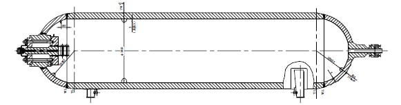
Figure 1 Structure diagram of high-pressure nitrogen gas storage tank
Main design parameters and structural characteristics of gas storage tanks
Main design input parameters
This equipment mainly provides a high-pressure nitrogen source for wind tunnel mechanics experiments, which needs to be deflated quickly. During deflation, the phenomenon of medium hanging on the wall is not allowed, and the deflation process can be completed instantly. Medium nitrogen, intermittent use, horizontal installation. The vessel is classified as Class III (SAD level), and the design standard JB 4732 "Steel Pressure Vessels-Analysis and Design" has a corrosion allowance of 0 (effective thickness of surfacing layer is 3mm). See Table 1 for design parameters.
Table 1 Design parameters
Structural characteristics and material selection
The gas storage tank is supported by two saddles. In order to reduce the thickness of the equipment shell, 20MnMo forging is used as the main material. In order to reduce the head thickness, the left and right heads are spherical heads. The equipment medium is nitrogen with high purity and high pressure. The equipment is not provided with a connecting pipe, and the left head is provided with a DN500 manhole. In order to reduce the opening of the shell, a DN40 air inlet is provided on the manhole cover of the left head and a DN65 air outlet is provided on the right head. The inner wall of E309MoL+E316L double-layer surfacing is adopted to protect its interior and meet the requirements of process cleanliness.
Design of the main structure
Design of self-tightening manhole structure
The pressure of this equipment is very high. If the manhole of DN500 is connected by a conventional flange, the flange bolts need to balance the pre-tightening force of the gasket and the internal pressure caused by the internal operating medium to meet the sealing requirements. Therefore, as the stress of bolts increases, and the required cross-sectional area of bolts increases, resulting in an increase in the number and diameter of bolts. The manhole flange designed according to the conventional flange connection has a large size,
The flange is very heavy, its disassembly is difficult and the cost is high. After design optimization, the manhole structure with a self-tightening seal [4] is adopted, and the manhole cover is set inside the equipment, and the bolts only need to provide an initial pre-tightening force to produce the initial seal. When the internal pressure of the equipment increases, the manhole cover is subjected to internal pressure, and the sealing gasket is pressed more tightly. The greater the internal pressure, the greater the sealing force produced by the manhole cover, and the better the sealing effect. See Figure 2 for the specific structure.
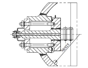
Figure 2 Self-tightening manhole structure
For the choice of manhole gasket, octagonal gasket and corrugated composite gasket are often used at the nozzle of high-pressure equipment. Considering the sealing performance and experience, an octagonal pad and corrugated composite pads can meet the sealing requirements. However, the manhole cover is inside the equipment, and the gasket can only be installed inside the equipment before the last circumferential seam of the cylinder is welded. Therefore, the above two gaskets cannot be replaced, and the heat treatment of the equipment will affect the sealing performance of the gaskets. Considering the replacement of the manhole gasket, the diameter of the gasket is elliptical, and the gasket can be replaced after the manhole is opened. However, the sealing force of the gasket with an elliptical diameter is uneven, so it cannot be accurately calculated, and it is easy to leak after long-term use. After investigation, the C-ring self-tightening sealing gasket is finally considered. This C-ring adopts a three-layer structure, as shown in Figure 3. Its advantage is that it can be slightly deformed, and it can be changed into an oval shape by slightly exerting a force in the radial direction of the annular cushion, and installed into the equipment from the manhole. Through demonstration with the C ring manufacturer, the determined seal groove structure is shown in Figure 4.
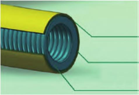
Fig. 3 C ring cross-section structure
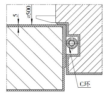
Fig. 4 C ring seal groove structure
Design of hinge mechanism
A manhole cover is inside, and the manhole cover is provided with an air inlet. In order to make the manhole cover open smoothly, a hinge mechanism is installed inside the equipment. The hinge mechanism can only move and rotate horizontally. The first step of opening the manhole is that the air inlet connecting pipe moves inward along the axis direction of the equipment until the flange of the air inlet connecting pipe completely enters the inside of the equipment; Secondly, the manhole cover is completely opened by the whole rotation. The manhole is closed in the opposite step, and the hinge mechanism has three rotating shafts to ensure the manhole is opened and closed smoothly. In the process of opening and closing the manhole, it is necessary to keep moving horizontally, and there is no displacement in the vertical direction. The hinge connecting rod is required to have sufficient strength and rigidity to balance the bending stress caused by gravity. The hinge mechanism is shown in Figure 5.
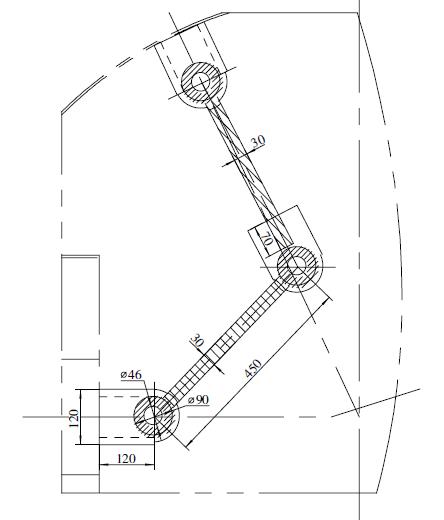
Figure 5 Hinge mechanism
Form of welded joint of shell
All pressure-welded joints of equipment require full-section penetration. According to the specifications and material characteristics of equipment, consider welding conditions, welding quality, etc., and determine a reasonable welding joint form. The equipment is under high-pressure fatigue conditions, and the excess height of the welding seam is required to be polished flush with the base metal. The welding joints between the connecting pipe and the shell are all in butt joint form. The wall thickness of the shell is thick, the circumferential welding joint of the shell adopts a U-shaped groove, and the welding joint between the connecting pipe and the shell adopts half a U-shaped groove on the shell, which reduces the consumption of welding materials and the welding workload in the welding process.
Finite element stress analysis and calculation
Because the design pressure of the equipment is higher than GB/T 150, and there are pressure fluctuations and harsh working conditions, it cannot be designed by the regular design method. It is necessary to analyze and design the equipment and check the strength and fatigue cumulative damage through finite element analysis. The equipment is designed, manufactured, inspected and accepted according to JB 4732 standards. The whole equipment is modeled, analyzed and calculated, and the full elastic material constitutive model is adopted. The nominal stress of Tresca of the equipment is obtained by elastic analysis. The stress intensity of the discontinuous part of the structure is evaluated by the linearization method, and the alternating stress amplitude Salt obtained by the stress of the equipment under fluctuating conditions is checked for fatigue accumulation.
And the total cumulative damage times of equipment in life. Normal Lagrange nonlinear contact algorithm is adopted for the connection between the manhole cover and equipment, the friction coefficient is set, and the contact compressive stress is checked. The Tresca stress nephogram calculated by the equipment is shown in Figure 6.
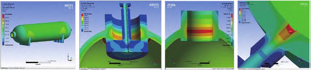
Fig. 6 stress nephogram of Tresca equipment
Manufacturing difficulties and technical requirements
Requirements of surface roughness
The equipment needs surfacing, processing, heat treatment and polishing, and the roughness requirement are better than 0.25 μm[5]. The polished parts include the inner wall of the equipment, girth weld, fillet weld and the surface of parts. In the polishing process, an industrial tank polisher, vertical lathe tool holder micro polisher, Chiba wheel and wire drawing wheel are used together. The shell adopts the plan of welding with electrodes and polishing, the inner wall of the connecting pipe is polished by a rolling knife, the manhole surface is polished by a micro-polisher+vertical lathe, and the shaft surface is polished by a micro-polisher+horizontal lathe. After polishing, the polishing effect is detected by polishing the reference block and roughness detector.
Welding requirements
The center of the left head has a large opening, so in order to prevent deformation when welding pipes are installed, the head port is provided with internal and external anti-deformation supports. After assembling and welding the nozzle, weld the inner end face of the nozzle with allowance. After welding the nozzle with the head and heat treatment, process the size of the sealing surface at the end of the nozzle and other parts based on the head port. The inlet flange and manhole cover are butt joints, and the welding amount is large. In order to prevent welding deformation, the manhole cover has a margin in the thickness direction. When assembling and welding the inlet nozzle flange and manhole cover, symmetrically and evenly tie the inlet nozzle flange and manhole cover, and then weld them twice. When the welding is halfway in the thickness direction, enter the furnace for annealing, and then weld them. After welding, anneal them to relieve stress, and then remove the tie bars. The surfacing of the cylinder requires machining. In order to ensure the effective thickness of the surfacing layer after machining and polishing, the surface thickness of the surfacing layer is increased to 6mm, that is, the total thickness of the surfacing layer is not less than 8mm. The cylinder joints are relatively short, and the circumferential seam between the cylinder joints and the circumferential seam between the cylinder and the left head is automatically welded to ensure the forming quality of the circumferential seam and facilitate the subsequent polishing of the circumferential seam.
Requirements for Dew Point Test
The equipment is required to carry out the -80℃ nitrogen dew point test, demonstrate the -80℃ dew point test, determine the influencing factors of the dew point test, and eliminate them one by one. The dew point test of the liquid nitrogen source is -80℃ to determine whether the medium can reach the dew point of -80℃. According to the standard, the dew point corresponds to the water vapor content one by one (-80℃ dew point water vapor content is 0.54×10⁶). In view of the large internal volume of the equipment, the method of quickly and efficiently reducing the water content should be determined to ensure that the -80℃ dew point test can be realized. Finally, the dew point test of the equipment is completed by gradual replacement.
Concluding remarks
The gas storage tank bears high pressure and fatigue load, and users have special requirements. It is necessary to master the key points of the above structural design and solve the difficulties in the manufacturing process, so as to design reasonably and manufacture correctly. In the process of product design, the fatigue load is considered, the self-tightening sealing structure is adopted, and the C-ring sealing element which can deform slightly is selected. In the manufacturing process, by controlling the deformation of welding and heat treatment, polishing the inside of the equipment and replacing it with nitrogen, the product quality is finally guaranteed. This product fills many gaps in the design and manufacture of the new self-sealing structure of Lanshi Company and enhances the competitiveness of Lanshi Company in similar products. It has promoted the expansion of the military market and achieved the expected technical indicators and market effects.
Figure 1 Structure diagram of high-pressure nitrogen gas storage tank
Main design parameters and structural characteristics of gas storage tanks
Main design input parameters
This equipment mainly provides a high-pressure nitrogen source for wind tunnel mechanics experiments, which needs to be deflated quickly. During deflation, the phenomenon of medium hanging on the wall is not allowed, and the deflation process can be completed instantly. Medium nitrogen, intermittent use, horizontal installation. The vessel is classified as Class III (SAD level), and the design standard JB 4732 "Steel Pressure Vessels-Analysis and Design" has a corrosion allowance of 0 (effective thickness of surfacing layer is 3mm). See Table 1 for design parameters.
| Parameter | Numerical Value | Parameter | Numerical Value |
| Design Temperature (MPa) | 36.8 | Design Temperature (℃) | -20 - 80 |
| Body Material | 20MnMo Forge+ Overlaying | Air Inlet | DN40 |
| Design Life | 20 | Air Outlet | DN65 |
| Volume (m3) | 20 | Manhole | DN500 |
Structural characteristics and material selection
The gas storage tank is supported by two saddles. In order to reduce the thickness of the equipment shell, 20MnMo forging is used as the main material. In order to reduce the head thickness, the left and right heads are spherical heads. The equipment medium is nitrogen with high purity and high pressure. The equipment is not provided with a connecting pipe, and the left head is provided with a DN500 manhole. In order to reduce the opening of the shell, a DN40 air inlet is provided on the manhole cover of the left head and a DN65 air outlet is provided on the right head. The inner wall of E309MoL+E316L double-layer surfacing is adopted to protect its interior and meet the requirements of process cleanliness.
Design of the main structure
Design of self-tightening manhole structure
The pressure of this equipment is very high. If the manhole of DN500 is connected by a conventional flange, the flange bolts need to balance the pre-tightening force of the gasket and the internal pressure caused by the internal operating medium to meet the sealing requirements. Therefore, as the stress of bolts increases, and the required cross-sectional area of bolts increases, resulting in an increase in the number and diameter of bolts. The manhole flange designed according to the conventional flange connection has a large size,
The flange is very heavy, its disassembly is difficult and the cost is high. After design optimization, the manhole structure with a self-tightening seal [4] is adopted, and the manhole cover is set inside the equipment, and the bolts only need to provide an initial pre-tightening force to produce the initial seal. When the internal pressure of the equipment increases, the manhole cover is subjected to internal pressure, and the sealing gasket is pressed more tightly. The greater the internal pressure, the greater the sealing force produced by the manhole cover, and the better the sealing effect. See Figure 2 for the specific structure.
Figure 2 Self-tightening manhole structure
For the choice of manhole gasket, octagonal gasket and corrugated composite gasket are often used at the nozzle of high-pressure equipment. Considering the sealing performance and experience, an octagonal pad and corrugated composite pads can meet the sealing requirements. However, the manhole cover is inside the equipment, and the gasket can only be installed inside the equipment before the last circumferential seam of the cylinder is welded. Therefore, the above two gaskets cannot be replaced, and the heat treatment of the equipment will affect the sealing performance of the gaskets. Considering the replacement of the manhole gasket, the diameter of the gasket is elliptical, and the gasket can be replaced after the manhole is opened. However, the sealing force of the gasket with an elliptical diameter is uneven, so it cannot be accurately calculated, and it is easy to leak after long-term use. After investigation, the C-ring self-tightening sealing gasket is finally considered. This C-ring adopts a three-layer structure, as shown in Figure 3. Its advantage is that it can be slightly deformed, and it can be changed into an oval shape by slightly exerting a force in the radial direction of the annular cushion, and installed into the equipment from the manhole. Through demonstration with the C ring manufacturer, the determined seal groove structure is shown in Figure 4.
Fig. 3 C ring cross-section structure
Fig. 4 C ring seal groove structure
Design of hinge mechanism
A manhole cover is inside, and the manhole cover is provided with an air inlet. In order to make the manhole cover open smoothly, a hinge mechanism is installed inside the equipment. The hinge mechanism can only move and rotate horizontally. The first step of opening the manhole is that the air inlet connecting pipe moves inward along the axis direction of the equipment until the flange of the air inlet connecting pipe completely enters the inside of the equipment; Secondly, the manhole cover is completely opened by the whole rotation. The manhole is closed in the opposite step, and the hinge mechanism has three rotating shafts to ensure the manhole is opened and closed smoothly. In the process of opening and closing the manhole, it is necessary to keep moving horizontally, and there is no displacement in the vertical direction. The hinge connecting rod is required to have sufficient strength and rigidity to balance the bending stress caused by gravity. The hinge mechanism is shown in Figure 5.
Figure 5 Hinge mechanism
Form of welded joint of shell
All pressure-welded joints of equipment require full-section penetration. According to the specifications and material characteristics of equipment, consider welding conditions, welding quality, etc., and determine a reasonable welding joint form. The equipment is under high-pressure fatigue conditions, and the excess height of the welding seam is required to be polished flush with the base metal. The welding joints between the connecting pipe and the shell are all in butt joint form. The wall thickness of the shell is thick, the circumferential welding joint of the shell adopts a U-shaped groove, and the welding joint between the connecting pipe and the shell adopts half a U-shaped groove on the shell, which reduces the consumption of welding materials and the welding workload in the welding process.
Finite element stress analysis and calculation
Because the design pressure of the equipment is higher than GB/T 150, and there are pressure fluctuations and harsh working conditions, it cannot be designed by the regular design method. It is necessary to analyze and design the equipment and check the strength and fatigue cumulative damage through finite element analysis. The equipment is designed, manufactured, inspected and accepted according to JB 4732 standards. The whole equipment is modeled, analyzed and calculated, and the full elastic material constitutive model is adopted. The nominal stress of Tresca of the equipment is obtained by elastic analysis. The stress intensity of the discontinuous part of the structure is evaluated by the linearization method, and the alternating stress amplitude Salt obtained by the stress of the equipment under fluctuating conditions is checked for fatigue accumulation.
And the total cumulative damage times of equipment in life. Normal Lagrange nonlinear contact algorithm is adopted for the connection between the manhole cover and equipment, the friction coefficient is set, and the contact compressive stress is checked. The Tresca stress nephogram calculated by the equipment is shown in Figure 6.
Fig. 6 stress nephogram of Tresca equipment
Manufacturing difficulties and technical requirements
Requirements of surface roughness
The equipment needs surfacing, processing, heat treatment and polishing, and the roughness requirement are better than 0.25 μm[5]. The polished parts include the inner wall of the equipment, girth weld, fillet weld and the surface of parts. In the polishing process, an industrial tank polisher, vertical lathe tool holder micro polisher, Chiba wheel and wire drawing wheel are used together. The shell adopts the plan of welding with electrodes and polishing, the inner wall of the connecting pipe is polished by a rolling knife, the manhole surface is polished by a micro-polisher+vertical lathe, and the shaft surface is polished by a micro-polisher+horizontal lathe. After polishing, the polishing effect is detected by polishing the reference block and roughness detector.
Welding requirements
The center of the left head has a large opening, so in order to prevent deformation when welding pipes are installed, the head port is provided with internal and external anti-deformation supports. After assembling and welding the nozzle, weld the inner end face of the nozzle with allowance. After welding the nozzle with the head and heat treatment, process the size of the sealing surface at the end of the nozzle and other parts based on the head port. The inlet flange and manhole cover are butt joints, and the welding amount is large. In order to prevent welding deformation, the manhole cover has a margin in the thickness direction. When assembling and welding the inlet nozzle flange and manhole cover, symmetrically and evenly tie the inlet nozzle flange and manhole cover, and then weld them twice. When the welding is halfway in the thickness direction, enter the furnace for annealing, and then weld them. After welding, anneal them to relieve stress, and then remove the tie bars. The surfacing of the cylinder requires machining. In order to ensure the effective thickness of the surfacing layer after machining and polishing, the surface thickness of the surfacing layer is increased to 6mm, that is, the total thickness of the surfacing layer is not less than 8mm. The cylinder joints are relatively short, and the circumferential seam between the cylinder joints and the circumferential seam between the cylinder and the left head is automatically welded to ensure the forming quality of the circumferential seam and facilitate the subsequent polishing of the circumferential seam.
Requirements for Dew Point Test
The equipment is required to carry out the -80℃ nitrogen dew point test, demonstrate the -80℃ dew point test, determine the influencing factors of the dew point test, and eliminate them one by one. The dew point test of the liquid nitrogen source is -80℃ to determine whether the medium can reach the dew point of -80℃. According to the standard, the dew point corresponds to the water vapor content one by one (-80℃ dew point water vapor content is 0.54×10⁶). In view of the large internal volume of the equipment, the method of quickly and efficiently reducing the water content should be determined to ensure that the -80℃ dew point test can be realized. Finally, the dew point test of the equipment is completed by gradual replacement.
Concluding remarks
The gas storage tank bears high pressure and fatigue load, and users have special requirements. It is necessary to master the key points of the above structural design and solve the difficulties in the manufacturing process, so as to design reasonably and manufacture correctly. In the process of product design, the fatigue load is considered, the self-tightening sealing structure is adopted, and the C-ring sealing element which can deform slightly is selected. In the manufacturing process, by controlling the deformation of welding and heat treatment, polishing the inside of the equipment and replacing it with nitrogen, the product quality is finally guaranteed. This product fills many gaps in the design and manufacture of the new self-sealing structure of Lanshi Company and enhances the competitiveness of Lanshi Company in similar products. It has promoted the expansion of the military market and achieved the expected technical indicators and market effects.
